Equipping any wireless-enabled device with an antenna involves making several decisions. In this article, part 1 of a two-part series, we highlight some of the key characteristics important when selecting a suitable antenna. We delve into the antenna terminology and specifications you will encounter when reviewing a datasheet. Topics include the frequency range the device operates within, antenna gain, and radiation pattern. Mechanical factors such as ingress protection, internal or external placement, and mounting method are also important.
A good antenna is essential to establishing a reliable and resilient wireless link
No doubt we have all walked around or held our cell phones high to improve reception when in an area of poor signal strength. Any wireless link performance is enhanced when there are no obstacles in the path between transmitter and receiver. Trees, walls, weather and terrain absorb radio frequency signals, reducing the distance over which devices can establish a good link, whether data or voice. Equipping a wireless device with a well-matched antenna mitigates the impact factors that reduce the signal strength have. An optimal antenna ensures that the maximum generated radio frequency power from the transmitter’s final stage is radiated into the air; likewise, at the receiver’s detection stage, as much as the signal reaching the antenna can be processed. As we’ll discover in part 2, the connecting cable, technically termed the transmission line, and the associated connectors also impact antenna performance.
Antenna parameters
From a simplistic perspective, a length of wire is an antenna, and there is a relationship between the wire’s optimal length for use at a particular frequency. The term wavelength refers to the distance between adjacent peaks of a wireless signal. It is used to determine an antenna’s physical length and characteristics and indicates the point of resonance. For example, a Wi-Fi signal operating at 2.4 GHz has a wavelength of 12.5 cm, using the formula wavelength in meters(m) = speed of light/frequency (Hz). The speed of light is a constant of 299,792,458 m/s, often approximated to 3×10⁸. The length of an antenna is described relative to its operating wavelength, for example, a quarter-wave, half-wave, or full-wave.
Most popular data and voice wireless communication methods used today, such as Wi-Fi, Bluetooth, Cellular communication (4G – 5G), and ISM applications (industrial, scientific, and medical), involve frequencies from 400 MHz to 3.4 GHz. At these frequencies, the antenna’s physical length becomes increasingly shorter, permitting various construction methods, including fabrication on a PCB.
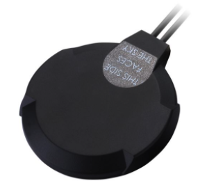
Many antennas, particularly those used for automotive, transportation, and telemetry applications, are packaged with multiple antennas inside to cater for Wi-Fi, GPS/GNSS, vehicle-to-vehicle/vehicle-to-infrastructure/vehicle-to-anything (V2V/V2I/V2X), and LTE cellular communication. An example is the Taoglas Optimus MA220. See Figure 1. This externally mounted antenna is IP67 waterproof rated.
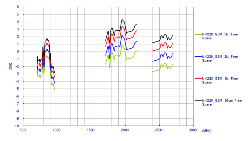
Antenna gain: The design and construction of some antennas make them more efficient at radiating and receiving than a standard antenna model. On the datasheet, this factor is expressed as the gain and is measured in dBi (dB isotropic). For example, Figure 2 illustrates the performance of the Taoglas MA220 for LTE cellular communication.
Radiation pattern: Some antennas have directional capabilities, meaning they are more effective at radiating and receiving in certain directions or specific planes. An antenna with an isotropic radiation pattern means it emits the same amount of energy in all directions. An omnidirectional antenna radiates the same amount of energy in a specific plane, horizontally or vertically.
Antenna impedance: The impedance of an antenna changes with frequency. It is vitally important to match the antenna to the output impedance of the transmitter’s power output stage and, likewise, the receiver’s front-end. In part 2 of this article, we’ll also learn how the impedance of the connecting cable and connectors are also critical to achieving a good match. An impedance of 50 Ohm is a popular standard.
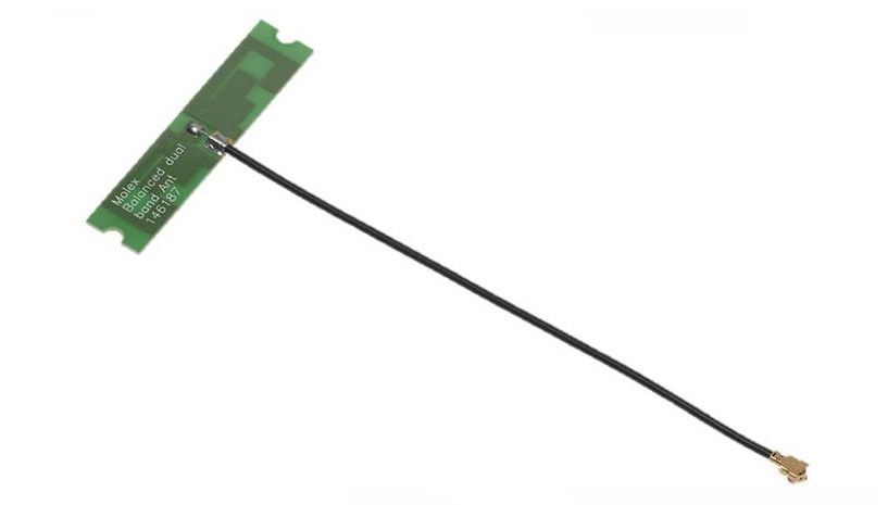
Antenna bandwidth: The frequency range over which the antenna is effective is called the bandwidth. Bandwidth is typically quoted based on a centre frequency. An example of a PCB antenna is the Molex Wi-Fi PCB antenna.
It has a bandwidth of 100 MHz on a centre frequency of 2.45 GHz, an impedance of 50 Ohm, and a 3.2 dBi gain.
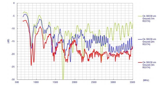
VSWR & return loss: Return loss measures how well matched an antenna is to a transmitter and its transmission line (the coaxial cable). Return loss measures how much power is reflected back to the transmitter instead of being radiated and is measured in dB. The higher the (negative number), the better the antenna’s performance. The voltage standing wave ratio (VSWR) is another way to measure return loss. An antenna should have a return loss better than -10 dB (VSWR 2). Figure 4 illustrates the return loss characteristics of the Taoglas GA110 cellular antenna.
Measurement of antenna parameters
A vector network analyser (VNA) is used to measure the impedance and return loss characteristics of an antenna and its transmission line. Portable, low cost (< 150 Euro) VNAs provide adequate measurement resolution, but a more professional bench-mounted unit costing greater than 5,000 Euro is more suitable for lab-based work. High-end RF spectrum analysers often incorporate a VNA function. A VNA also aids in achieving the correct design of capacitor- and inductance-based matching networks between the transmitter and the transmission line.
Antenna datasheet parameters; no longer a mystery
This short article explains some of the key specification parameters you will likely encounter when reading an antenna datasheet. With this information, you will have a better insight into the best antenna for your application, giving optimal performance. In part 2, we will investigate the role of antenna cables and popular antenna connectors.