


Timekeeping is a crucial feature of most electronic gadgets, and timing components are a staple for most electronic circuits. The timing industry today is mainly dominated by quartz- based devices owing to their efficiency in generating stable frequencies which ensure precise data transmission at a low cost. With the emergence of technologies like 5G and Wi-Fi, there is an even greater need to enhance the quality of experience for end-users. Therefore, it becomes imperative to choose the correct timing solution that perfectly complements Original Equipment Manufacturers’ (OEMs) and design engineer’s cutting-edge applications and high-performance demands.
The two commonly used frequency devices utilised in timing applications are quartz crystals and oscillators. Crystals are passive components and can only function when connected to an external oscillator circuit which is usually present in most microprocessors. On the other hand, an oscillator does not require external circuitry to function as it consists of a resonating crystal along with an oscillator IC as a single device. Oscillators are the go-to option for frequency control as they require less design knowledge to implement as an all in one solution. However, quartz crystals are preferred by experienced designers who have the expertise in choosing the best crystal to improve the oscillator’s performance thereby leading to optimised performance.
Nonetheless, choosing the right frequency device for optimum functionality involves more than just operation type; it largely depends on the characteristics of crystals and oscillators, which will be discussed below.
What Makes a Good Timer?
Operating Frequency: Each application has a corresponding operating frequency range since it is crucial to ensure that there is no overlapping of signals. For instance, the frequency 32.768 kHz is utilised to provide timing for digital watches, while 26 MHz is essential for GPS functioning. The 13 MHz frequency is employed in GSM, and 13.560 MHz frequency is commonly used for Radio Frequency Identification (RFID). Selecting a frequency device that aligns with its specific application is a critical factor when choosing crystals and oscillators.
Frequency Stability: Every crystal has an inherent frequency at which it resonates, this is due to the crystal’s innate piezoelectric property. Frequency stability is the normal deviation from that nominal frequency. This deviation can result from various external factors, predominantly temperature variations, but also due to fluctuations in supply voltage, load capacitance value, or even excess heat due to soldering.
Tighter stability components are fine-tuned to provide more accurate timing than those with wider stability ranges. Within IQD’s product range, there are many options to choose from, including temperature compensated oscillators (TCXOs) with stability as low as ±0.05ppm, or oven controlled oscillators (OCXOs) like IQOV-164 with stabilities at the scale of ±20ppb.
Temperature Threshold: Temperature is the most influential external factor affecting the performance of timing devices. As the temperature varies, the frequency also moves. The movement of frequency is given by a term called frequency stability. The stability accuracy of quartz is dictated by the angle that the quartz bar is cut at during manufacture. Small changes in the cut-angle dictate the performance achieved over temperature.
Below is a table of some of the common applications along with their corresponding operating temperature range.
| Applications | Operating Temperature Range |
| Commercial, Automotive Grade 4 | 0 to 70ºC |
| Extended Commercial | -20 to70ºC |
| Industrial, Automotive Grade 3 | -40 to 85ºC |
| Extended Industrial, Automotive Grade 2 | -40 to 105ºC |
| Automotive Grade 1 | -40 to 125ºC |
| Military/Automotive Grade 0 | -55 to 125ºC and above |
The popular IQXC-180 Auto, CFPX-180 and IQXC-42 used in automotive applications all have a wide operating temperature range from -40 to 125ºC and several other tighter temperature ranges.
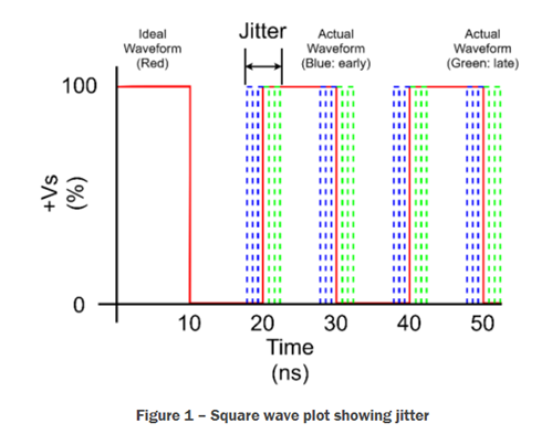
Phase Noise & Jitter: Phase noise refers to the random fluctuation in the phase or frequency of a signal. It can disrupt accuracy, resolution, and adversely affect the Signal to Noise Ratio (SNR). Jitter, on the other hand, introduces inconsistencies in the time domain of signal and can lead to bit error rates (BER). Depending on the specific application, a designer should select the timing device that has both low phase noise and jitter. These factors are important in some of the most prominent applications such as navigation, digital communication, audio processing and radar technology.
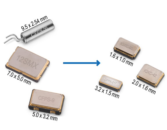
Package Dimension: The package size of components holds significant importance in the design considerations of Printed Circuit Boards (PCBs). As consumer gadgets continue to reduce in size, selecting suitably sized internal components becomes integral. Although crystals are smaller in size to their oscillator counterparts, they require additional capacitors and circuitry to generate a timing pulse. Therefore, oscillators can be the preferred option when space is a constraint in circuit designing as they reduce the PCB footprint since it is an all-in-one package.
IQD’s catalogue consists of both crystals and oscillators that are hermetically sealed, making them more ruggedised and are available in SMD packages that are as small as 1.6 x 1.0 mm, 1.6 x 1.2 mm in addition to the industrial standard size 2.0 x1.6 mm.
Output Signal Type for Oscillators: Chipset vendors must specify the correct input for their timing device. An oscillator’s output can be single-ended or differential type. Single-ended outputs are specifically used for frequencies below around 100 MHz whereas differential outputs are used for high frequencies to reduce overall system noise.
Another emphasis should be matching the oscillator output signal with the correct load otherwise issues may arise with signal amplitude, rise and fall times, duty cycle and start-up time. Below are common single-ended output types of an oscillator:
• CMOS (complementary metal oxide semiconductor)
• HCMOS (high-speed CMOS)
• LVCMOS (low-voltage CMOS)
Differential outputs are comparatively more complex to design but offer superior performance in high-frequency applications, as any noise common to the differential signal cancels out. Differential signal types include:
• PECL (positive emitter-coupled logic)
• LVPECL (low-voltage PECL)
• CML (current-mode logic)
• LVDS (low-voltage differential signalling)
• HCSL (high-speed current-steering logic)
Low Power Operation for Oscillators: Many oscillators feature a built-in enable/disable pin as a fundamental component of their functionality. When the device is disabled, the internal oscillator ceases operation, transitioning into a standby mode that consumes less current. This becomes particularly beneficial as many electronics manufacturers prioritise power efficiency, especially in small-sized battery-operated devices. Thus, oscillators optimised for low voltage supply are the best go-to components when the focus is on low power considerations.
Cost concern: A single crystal package will be more cost-effective than an oscillator. However, when factoring in engineering expenses along with part costs, oscillators may emerge as an economical option in circuit design. In certain scenarios, the decision to use crystals may prove even more costly, especially if services and testing are outsourced. It’s important not to overlook the additional expenses arising from supplementary components such as load capacitors and resistors, as well as from processes such as PCB respinning for improved signal performance.
Furthermore, quartz crystals are better suited for situations where manufacturers wish to create their own electronic oscillators, giving them the flexibility to optimise all relevant parameters according to their specific projects. Conversely, oscillators hold an advantage in reducing the bill of materials (BOM) and PCB space. Thus, decisions influenced by cost may be grounded in the quality of applications and the scale of production.
FAQs
The resonating function of a quartz crystal is by cutting it at an appropriate orientation with respect to the quartz bars crystallographic axis. This axis helps in defining the coordinates of the crystal lattice. This is traditionally designated as a crystal blank, which is then placed between two electrodes to pass an AC voltage through it. Due to the crystal’s piezoelectric properties, the applied voltage leads to a mechanical shift in the crystal, causing it to vibrate.
When the frequency of the applied voltage aligns to the crystal’s mechanical resonance the amplitude of the vibration becomes large. This also leads to an increase in accompanying current, causing a decrease in the magnitude of the effective impedance of the device. Simultaneously, the displacement current also increases, further contributing to the decrease in the magnitude of the effective impedance. The sudden change in impedance as the voltage and resonant frequency varies is the key factor in the application of the quartz crystals as a frequency control element in crystal oscillators.
Conversely, oscillators operate with a different mechanism to crystals, utilising an inverse piezoelectric effect. The applied electric field will induce mechanical deformation across some materials, thus eventually utilising the vibrating crystal’s resonance for generating an electrical signal of a particular frequency. The fundamental distinction between the two-timing components is that crystals are not inherently as multi-featured as oscillators; a crystal is a component that is used in the construction of an oscillator.
Start-up time denotes the duration required for an oscillator to attain its resonant frequency upon the initial application of power. Usually, the start-up time for oscillators should be as low as a few milliseconds (ms).
Start-up time is a more common problem associated with low-frequency crystals than their high-frequency counterparts. Start-up times are also predominantly affected by the rise time of the power supply. A more rapid rise time results in a quicker start-up period compared to a crystal with a slower rise time. Start-up time can also result in an insufficient loop gain.
Want to find out more about crystals and oscillators? Listen to the second episode of the KnowHow Podcast below, where we have a chat with IQD’s Engineering Director, Nick Amey. Or alternatively, read our article.
This post was written by The Application Support Team at IQD Frequency Products.


