


In part 1 of this series, we explored an antenna’s importance in providing a reliable and resilient data or voice communications link. In this concluding part, we investigate how selecting the correct cable and connector are equally crucial.
As we discovered from part 1, the performance of a wireless transmitter relies on every component, from the output of the transmitter power amplifier stage to the antenna, including the transmission line and the connectors used. This approach is equally important for the received signal path, where low µV signals are involved. For most low power RF applications, such as Wi-Fi, Bluetooth, LTE, the transmission line is straightforward, typically just a length of coaxial cable.
Coaxial cable specifications
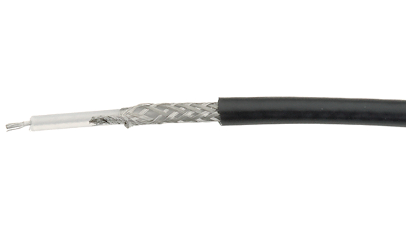
A typical coaxial (usually abbreviated to coax) cable comprises an inner centre conductor, typically copper, surrounded by a dielectric plastic core, which in turn is covered by one or more conductive layers, and then a final external sheath. The centre conductor may be a single solid core, or more typically, multiple strands. The outer conductor typically comprises a tinned copper braid, and sometimes, an additional copper foil to provide additional screening. The outer sheath, or jacket, provides an external protective layer to prevent moisture and dirt ingress, and physically protect the cable.
The overall diameter of a coax cable has a significant influence on its per-metre weight and minimum bending radius. However, electrical factors determine the construction method used and the types of suitable applications.
Key coax cable parameters
Characteristic impedance: Impedance is an essential selection criteria and needs to match the antenna at one end and the transmitter or receiver at the other end to achieve the highest signal transfer efficiency. Most coax cables are available with either a 50 Ohm or 75 Ohm impedance, with professional applications typically being 50 Ohm. The impedance of a coax cable is complex and may require an investigation of the dielectric capacitance between the centre and outer conductors.
Loss or attenuation: Equally important as selection criteria is a cable’s loss or attenuation characteristics. Typically quoted in dB per 100 metres and at a range of frequencies, the attenuation characteristics indicate how much transmitter power or received signal becomes lost along its length. The cable’s resistive and dielectric properties significantly influence its attenuation attributes.
Power handling capability: The maximum power handling of a cable depends on several factors, including peak operating voltages the dielectric can withstand, resistive losses that can manifest themselves as heat and impact the maximum operating temperature, and the return loss/VSWR of the antenna.
Velocity of propagation: In free space, an electromagnetic wave travels at the speed of light; however, within a coax cable, the capacitive and inductive properties, skin effect, and dielectric losses reduce the rate the signals propagate. Velocity impacts the phasing of transmitted and received signals, which may be critical with multiple antennas.
RF Coaxial cable examples
Several RF coax standards have evolved over the years, the most widely accepted being the RG system. Examples include RG58, RG59 and RG174.
RG58 – this 50 Ohm coax cable from Bedea – see Figure 1 – has an outer diameter of 5.0 mm, has a copper braid shield, and a 0.66 velocity factor. Attenuation per 100 m at 100 MHz is 15.2 dB, rising to 34.4 dB/100 m at 500 MHz. From a mechanical perspective, the minimum bending radius is 25 mm and weighs 36 kg/km.
RG59 – an example of a 75 Ohm impedance coax is the RG59 Flex from Tasker. With an outer diameter of 6.1 mm and a maximum voltage of 2,000 V. The attenuation characteristics are 15.7 dB/100m at 200 MHz and 33.6 dB/100m at 800 MHz.
RG174 (LMR-100A) – the diameter of this RG174 coax from Bedea measures 2.8 mm, has an impedance of 50 Ohm, and a maximum voltage rating of 1,100 V. At 200 MHz, the attenuation is 41.5 dB/100m and 68 dB/100m at 500 MHz.
RF connectors
RF connectors broadly fall into two categories. There are those suitable for mounting externally on equipment and those for use inside an enclosure. The majority of connectors used for interconnect tend to accommodate thicker coaxial cables, provide a degree of strain relief, and typically provide a means of locking plugs and sockets together. These connectors include N-type, TNC, BNC, UHF(PL259), SMA, and RPSMA (reverse polarity SMA).
RF connectors are also used to attach antennas internally, for example, from a wireless module to an internally affixed antenna, including u.Fl series from Hirose and the MHF series from IPEX. Both series feature a degree of cross-compatibility.
Like most connectors, they are specified by gender and typically accommodate a limited number of coaxial cable types. Most of the connectors identified here have maximum working frequencies into the tens of GHz. When selecting connectors, also check the return loss characteristics and the power handling capability.
Figure 2 illustrates a crimp-style SMA plug(male) from RND. The connector has a 50 Ohm impedance and is typically capable of operating up to 20 GHz. It has a brass housing of 7.9 mm diameter with a Teflon insulator and a gold-plated centre pin. The supported cable type is RG-174. A reverse gender series (RPSMA) is also available.
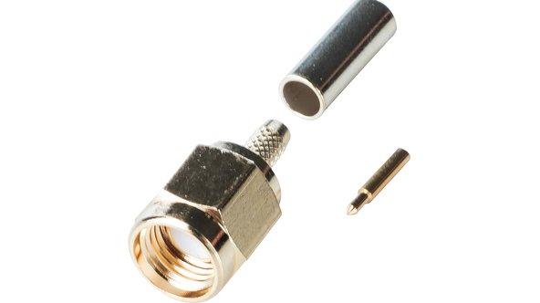
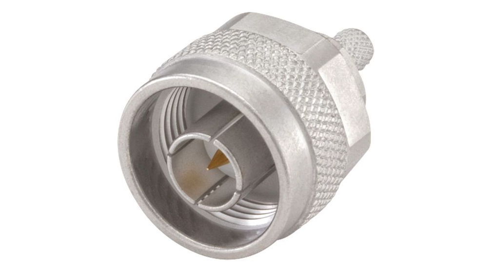
Figure 3 highlights an N-type plug from Rosenberger. Rated up to 11 GHz and capable of handling up to 1,000 W RF at 1 GHz, it features a return loss of better than 32 dB up to 2.5 GHz.
The u.FL connector is typically factory fitted to coaxial cables for antennas. It measures 2 mm and offers no strain relief or locking capability. u.FL sockets generally are surface mounted to PCBs. Figure 4 illustrates a u.FL to u.FL link cable from Würth Elektronik.

Selecting the correct antenna, coaxial cable and connectors for RF applications ensure wireless devices can achieve a reliable link. We’ve highlighted the key datasheet parameters you should review during the selection process in this short two-part series.


