Electrical safety is a vital aspect of any design, and several relevant standards apply to all forms of electrical equipment. For medical and healthcare equipment, the IEC 60601-1 safety standard applies and is designed to protect the patient and healthcare professionals. This requirement is particularly relevant where diagnostic and medical equipment may be attached to the patient and when medical staff are applying electrodes or operating the equipment. An essential aspect of IEC 60601 is that it applies not only to the equipment itself but also to the power supply.
In the case of a portable monitor, for example, that uses an external power supply plugged into a mains socket, the wall power adapter must comply with the specification. Virtually any imaging, diagnostic or monitoring equipment is covered by the specification, from large MRI installations to bedside heart rate monitors. The equipment, including power supplies and accessories, is assessed as a whole unit. The IEC 60601 safety standard was introduced in 1977 and has been adopted across the UK, Europe, the US, and Canada. Although in widespread adoption, there may be regional or country-specific interpretations of the standard, so if your product may be shipped worldwide, it is best to clarify any crucial differences.
Understanding IEC 60601 and associated terminology
The basic principles of the standard focus on isolation, protection from high voltages, and leakage current. Over the years, the standard has undergone several revisions, introducing improved safety limits, new technical concepts, and extending the scope to include additional safety factors. The current basic standard is the IEC 60601-1 3rd edition, which retains all the concepts from earlier standards. The collateral standard IEC60601-1-2 for “Electromagnetic disturbances, requirements and tests” has been already updated to 4th edition. This addition has been prompted by the increasing amount of wireless-connected medical devices, smartphones, and Wi-Fi connectivity now commonplace in hospitals and medical clinics.
Protection, through insulation and isolation, of patients and clinical staff from hazardous voltages is a core element of IEC 60601. From the standards perspective, a dangerous voltage is a supply above 42.2 VAC or 60 VDC. Essentially, the remit of isolation and insulation protection features is to provide one or more barriers between humans and the lethal voltages. Isolation typically uses physical distance to separate fatal voltages, and insulation involves using non-conductive materials as barriers.
Leakage current
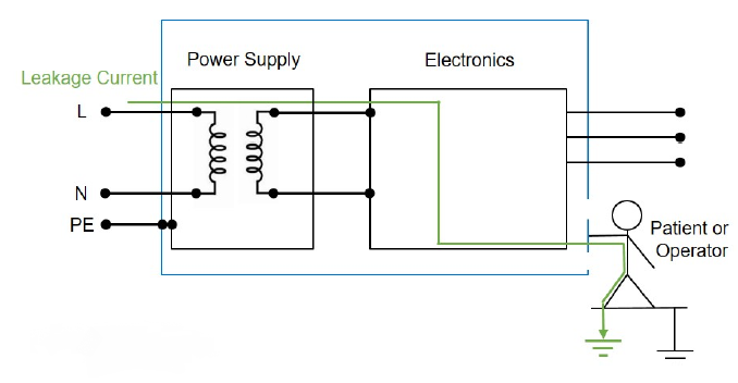
Figure 1 illustrates the basic concept of a leakage current (green line) from the live mains supply through the power supply and the unit’s electronics to the patient or operator. A protective earth (PE) connection grounds any conductive part of the unit, avoiding any external leakage current, but it can still occur from other parts of the unit. However, engineers cannot always rely on the reliability of a PE.
There are two classifications of products as a result. Also, insulation from hazardous voltages is defined as functional (necessary), protective (Class I only), basic (single), double (two independent methods), supplementary (single plus extra) or reinforced (single layer but equivalent to double).
- Class I product: This has at least one level of basic insulation and an additional form of protection provided by an earth/ground connection.
- Class II product: This has no protective earth connection and must have two layers of insulation – double or reinforced.
Within IEC 60601, there are limits defined for three distinct types of leakage current:
- Earth leakage current: is current that flows from the unit through the PE of a Class I product.
- Touch leakage current: is current that flows through the patient or operator if they touch the unit.
- Patient leakage current: is current that flows through the patient via an applied part, i.e., not the operator handling the medical equipment. This has several classifications depending on how an electrical connection is made to the patient.
Applied parts (AP) are defined as:
- B (body): Not normally conductive and can be released from the patient; may be connected to the earth. Examples include medical lasers and MRI body scanners.
- BF (body floating): Has conductive contact with the patient. Examples include ECG heart rate monitors and ultrasound scanners.
- CF (cardiac floating): Has or may have direct contact with the patient’s heart. An example is a dialysis machine.
Figure 2 illustrates a table of the maximum permitted leakage currents defined by IEC 60601-1 3rd edition in regular operation (RO) and for a single fault condition (SFC).

MOP, MOOP and MOPP
The IEC 60601-1 3rd edition standard introduced the means of protection (MOP) for medical and healthcare equipment and divided it into two categories to differentiate between a patient and the equipment operator.
Means of operator protection (MOOP): This can either be 1 MOOP or 2 MOOP. 1 x MOOP provides a ‘basic’ electrical insulation defined by the broad-ranging electrical equipment safety standard IEC 62368-1. 2 x MOOP requires reinforced insulation according to the same standard.
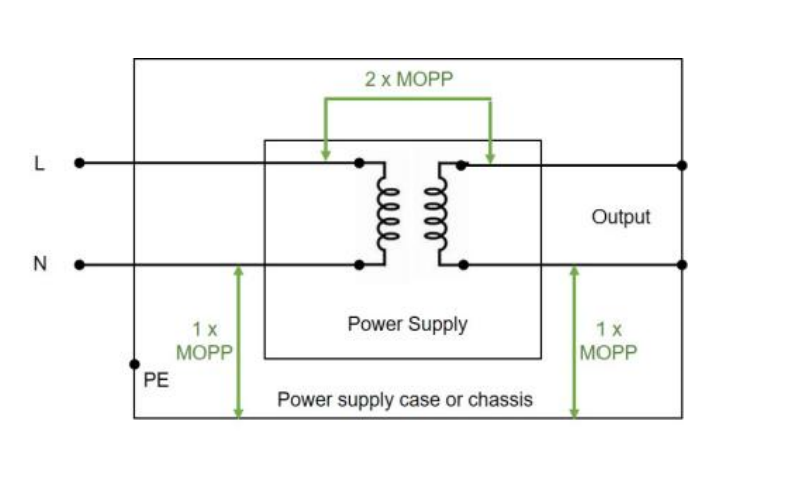
Means of patient protection (MOPP): Similar to MOOP but with increased requirements for insulation voltage and clearance/creepage defined within IEC 60601-1, 1 x MOPP requires just basic insulation, and 2 x MOPP requires has reinforced insulation.

The IEC 60601-1 stipulates the requirements for isolation, insulation, creepage and leakage current – see Figure 3. Creepage is the shortest distance along the surface of insulating material between two conductive parts. Clearance is the shortest air gap distance between conductive parts. Figure 4 illustrates a simplified view of MOPP in practice, with the electrical isolation provided by a transformer and wire insulation.
Selecting IEC 60601 compliant power supplies for medical and healthcare applications
TDK-Lambda is an industry-leading supplier of switched mode AC/DC and DC/DC medical and healthcare power supplies. The power supplies can be found across the globe in various equipment, from portable PET scanners, patient monitors, and dental apparatus to large MRI, X-ray, and CT installations.
The supplies are available in different formats, including open frame, encapsulated PCB mount, enclosed, and wall-mounted adapters. All supplies highlighted comply with the latest IEC 60601 standards. They also meet the EN55011 Class B standard for conducted and radiated electromagnetic interference.
TDK-Lambda WMM30 series
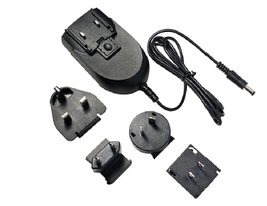
A series of plug-in wall-mounted single output 25 W to 30 W Class II AC/DC supplies with 2 x MOPP isolation suitable for use with B and BF applied parts. Six variants provide all the popular nominal output voltages from + 5 V to + 24 V via a barrel jack and offer an energy efficiency rating at 75 % load of typically 88 %. The WMM30 complies with the US and European energy-saving legislation and meets the DoE Level VI and EU Tier 2 no-load power efficiency ratings.
TDK-Lambda KM series
The lightweight Class II, 15 W to 40 W KM series, is packaged in a fully enclosed plastic resin case, and its compact dimensions make it suitable for PCB mounting. The series is available in a variety of single, dual, and triple output versions, covering popular nominal combinations from + 3 V to + 24 V, + 5 V /- 5V to + 15 V / – 15 V, and + 5V / + 12 V / – 12 V to + 5 V / + 15 V / – 15 V. It accommodates a wide input voltage range from 90 VAC to 264 VAC or + 100 VDC to + 375 VDC.

The KM series provides 2 x MOPP.
TDK-Lambda CUS100ME series
The 100 Watt convection-cooled CUS100ME series has an industry-standard 2 inch by 4 inch open-PCB construction and can be used for Class I or Class II applications. The series provides 2 x MOPP. Suitable for use with B and BF-rated equipment, the single-output supply covers all the popular nominals from + 12 V to + 48 V and has a typical energy efficiency rating up to 94 %.
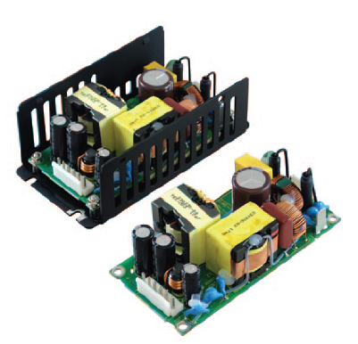
Other mounting options include U-channel, U-channel with cover, and baseplate cooled.
TDK-Lambda CUS30M and CUS60M series
Housed in a compact 2 inch x 3 inch industry-standard form factor, the 30 W CUS30M and 60 Watt CUS30M series of single output AC/DC power supplies are available with nominal output voltages ranging from 5 V to 48 V. The supplies can be used in either Class I or Class II installations and are suitable for B or BF applied parts. These convection-cooled power supplies also comply with the IEC 60601-1-2 edition EMI requirements.

The mounting options – illustrated in Figure 8 – include PCB mount, open frame, and enclosed.
TDK-Lambda CUS150M series
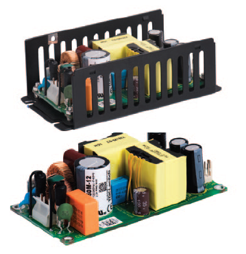
For higher power medical applications, the 150 W CUS150M series has 2 x MOPP and is constructed in an industry-standard space-saving 2 inch by 4 inch footprint – see Figure 9. Capable of operating in environments up to + 85 °C, the convection-cooled single output supply also has the option of a top-mounted fan enclosure. Other mounting options include U-channel, baseplate, and enclosed.
Powering medical and healthcare equipment
This short article has introduced the medical safety standard IEC 60601-1 and explained how patients and equipment operators are protected from exposure to dangerous voltages and leakage currents.
TDK-Lambda is a leading supplier of AC/DC and DC/DC power supplies that conform to the latest edition of the safety standard. The products highlighted are just a selection of the comprehensive range of TDK-Lambda power supplies available from Distrelec, an authorised distributor. Click the button below to find out more.


