Providing the power, control and actuation that underpins the ability to move is fundamental to modern robotics, which is why identifying the optimum power source, actuators, motors and drives needs to happen as early as possible in the robot design process.
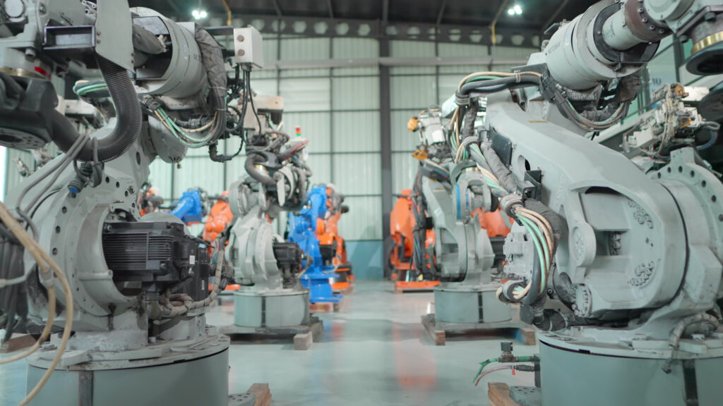
A fundamental factor guiding selection is the type of robot and its intended use. Within industry, robots take many forms, including cartesian, SCARA, cylindrical, delta, polar, gantry and articulated arm. Target applications include assembly, welding, machine tending, packaging, painting, pick and place, inspection and testing, to list but a few.
The type of power source is a primary consideration, particularly with regard to reliability, size, weight and lifecycle. To achieve optimised motion, robot OEMs also need to think about the most appropriate motor and actuators, and how these are best controlled.
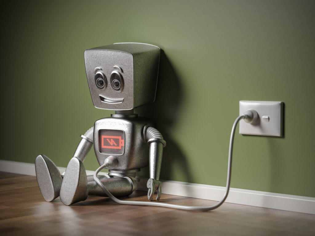
Batteries
Batteries are the most commonly selected source of electrical power and the question of which battery type is most suitable hinges on criteria such as safety, life cycle, weight and cost.
Both primary (non-rechargeable) and secondary (rechargeable) batteries are found in industrial robot applications. Although primary batteries present the obvious disadvantage of requiring replacement, they typically provide greater power for their size, making them suitable for certain light-drain applications. More often than not, however, rechargeable batteries are preferable.
Historically, the common types of rechargeable batteries for robot applications are nickel-cadmium (NiCd) and lead-acid. In addition, gelled lead-acid batteries, which are capable of providing power of up to 40 Wh/kg, have sometimes been deployed. Further secondary battery technologies include nickel-metal hydride (NiMH), silver-zinc and lithium-ion.

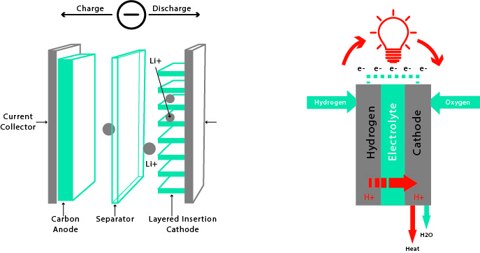
Now, however, lithium technologies have become the popular choice for today’s robot designers. Indeed, the performance, shelf-life and scalability of lithium-ion batteries – lithium battery banks can be scaled to meet most automation applications – have ensured wide appeal for the industrial robot arena. Among the many advantages of lithium-ion technologies is their light weight. Moreover, the lithium element itself is particularly reactive, which means it has the ability to store a lot of energy; typically around 150 Wh of electricity can be stored in 1 kg of battery. This compares favourably to a NiMH battery pack, which can store 60 to 100 Wh.
It is worth mentioning welding robots, commonly found in sectors such as automotive. Here, the same power source that feeds the welder can be used to power the robot’s electronic drives and motion-control components, and for these applications inverter power sources prove popular. Some of the latest inverter technologies automatically adjust input power while maintaining a constant output, and provide power surge blockers to ensure performance is unaffected by the simultaneous use of other devices requiring high current.
Clearly, battery geometry is highly influential when it comes to selection and robot type, and form will dictate which battery types should be included in the decision-making process. Similarly, weight is a significant factor and may depend on whether the robot is intended to be portable or fixed.
Also, as competitive advantage can be built on the time that a robot is able to run before additional charge is required, durability and capacity will be key aspects of the life cycle element of the battery selection equation.
Photovoltaic (PV) cells
Although the use of solar power has brought benefits to many areas of the engineering world, it has yet to find its place in industrial robotics. Some biology, electronic, aesthetics and mechanics (BEAM) robots, such as automated lawn mowers and vacuum cleaners, do currently use PV technology. The common configuration sees a solar cell, via appropriate circuitry, charge a capacitor to a set voltage level and then discharge it through the motor(s).
Upscaling this technology to industrial robots has yet to occur on a commercial level. There are a number of reasons behind the lack of progress, but mainly it’s due to the rather low power density of solar cells (Wp/m2), which is insufficient for most modern industrial robots.
Fuel cells
A far more likely future replacement for conventional batteries in industrial robots is fuel-cell technology, which is able to generate electricity by combining hydrogen, methanol or simple alcohol with oxygen. At present, cost is the restrictive barrier, but this could change as fuel cells are adopted in wider consumer markets.

Fuel cells supply energy by deriving power from a hydrocarbon source at high efficiencies of up to 75%. A typical configuration includes two electrodes located either side of a conductive electrolyte. Current is generated using a concept similar to that of fuel combustion, whereby protons are allowed to pass through the membranes and electrons are forced to bypass from anode to cathode via the electric circuit. Fuel-cell efficiency can be increased even further by making use of waste heat.
Actuators
With the decision about the power source complete, attention turns to the actuator technologies and motors needed for linear and rotational motion.
Stepper motors
Stepper motors are typically found in applications where cost is the primary factor, such as in common pick-and-place robotic devices. Among the principal benefits are high-accuracy positional control – which is why they are often used for systems such as 3D printers and CNC milling machines. This is because stepper motors are specifically designed to offer high holding torque, which in turn provides the ability to step incrementally to the next position. They can be used to advantage in applications where there is a defined need to control rotational angle, speed, position and synchronism. Furthermore, because stepper motors deliver maximum torque at low speeds they are a good choice for applications requiring low speed and high precision.
While stepper motors proved popular in early robot applications, their use has reduced in recent years. Among the reasons for this are factors such as efficiency, the need for encoders or limit switches to establish reference positions, and the potential for missed steps if overloaded. However, just as likely is the advent of more advanced brushless AC servomotor technology.
Servomotors
While many early electric robots used DC servomotors (as they give reasonable power output with a good degree of speed and positional control), most new industrial robots use brushless AC servomotors. Such motors offer the benefits of higher power output and virtually silent operation, while the absence of a brush means these high-torque devices are highly reliable and require virtually no maintenance.
Servos also have an inherent benefit in that they provide a high degree of angular precision, rotating only as much as requested before waiting for the next signal.
The principal difference between digital and analogue servos is the signal and how it is processed from the receiver to the servo, and how the servo uses this information to send power to the motor. Analogue servos control motor speed by giving on/off voltage signals to the motor, whereas digital servos feature a small microprocessor that analyses the receiver signals and processes them into very high-frequency voltage pulses to the motor.
Unlike analogue servos, which send out 50 pulses per second, an advantage of digital servos is their ability to send pulses upwards of 300 pulses per second. The pulses are shorter in length, but with so many voltage pulses, the motor accelerates faster and provides constant torque. With digital servos, the amount of power sent to the motor can also be adjusted to optimise performance and precision.
Efficiency, size, accuracy, reliability, speed and torque
Selecting the optimum motor is one of the most important parts of a robotics project and is based on considerations that include torque, speed, precision, voltage, cost and form factor.

In a robot, motor torque is typically conveyed to a wheel or actuator that subsequently prompts rotational or linear robotic motion. To estimate the required torque, engineers need to determine the mass of intended maximum payload, as well as the system’s static, dynamic and rolling friction.
For wheeled robots, it is important to specify the speed that the wheels need to turn. With faster speeds, there is usually a trade-off with precision. Ultimately, to achieve the accuracy required of robotic arms, servomotors are the popular pick chiefly because they have internal position regulation and are geared down to lower speeds, resulting in very precise position control.
Another important consideration is operating voltage. Before planning what battery packs will be used in the project, it is best to determine the nominal voltage when the motor runs. Usually, the higher the voltage, the higher the motor speed. The ‘voltage constant’ on the motor datasheet can be used to determine the speed-per-volt.
Hydraulic and pneumatic alternatives
Hydraulics were a fairly common sight on early robots as this technology is more rigid and controllable than pneumatics, and could provide greater power than the electric drives available at the time. Hydraulics also offer the potential to create a large reduction ratio.
The principal disadvantage of hydraulics is the comparatively slow pace of operation, while the high pressures involved mean that leaks can be problematic.
In terms of pneumatics, many simple pick-and-place systems are driven using compressed air, which introduces a level of affordability but has the disadvantage of being difficult to control. Essentially, the compressability of air introduces an additional ‘dead-time dynamic’ to the system that makes control more challenging.
Pneumatics are also used with a number of industrial robots to drive end effectors; pneumatic cylinders can deliver large forces and are a good choice for larger grippers. It is also possible, although fairly uncommon, for some robots to use pneumatic cylinders to move their body using an onboard bottle of pressurised air as the power source. The factor limiting wider adoption tends to be that pneumatics can only produce relatively small and simple back-and-forth motions.
Choosing the right motor-control technologies
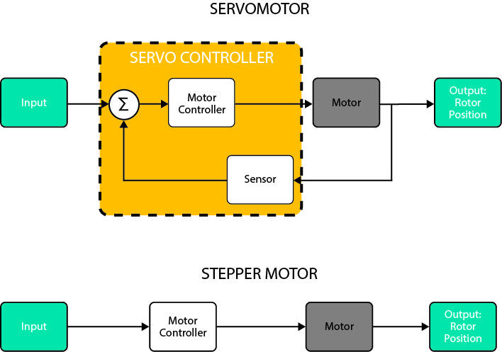
Choosing between a servomotor and a stepper motor comes down to a trade-off between complexity and control certainty. A stepper motor is simpler in configuration because, unlike a servomotor, it does not require an encoder. This design concept makes stepper motors simpler to control, but only if the robot has low performance requirements. Any robotics engineer wanting to push stepper motors close to their limit will find they become far more difficult to predictably control.

One of the benefits associated with stepper motors is their ability to be controlled in an open-loop system. Open-loop control means there is no requirement for feedback information concerning position, thus eliminating any need for encoders or resolvers, and the costs these incur. Position is known simply by keeping track of the input step pulses.
Servomotors are used in closed-loop systems with a digital controller that sends velocity commands to a driver amplifier, which in turn feeds the servomotor. A feedback device (encoder or resolver) provides information on the servomotor’s position and speed. To break it down further, the device is controlled by a feedback signal generated by comparing output signal and reference input signal.
As a result of the closed-loop system, a servomotor can operate with a specific motion profile programmed into the controller. Servomotors are controlled using a principle called pulse width modulation (PWM), with the angle of rotation determined by the duration of the applied pulse.


